The easiest way to find out what is going on in your project is to run Metal Frame Capture. That’s the little M icon above the debug console.
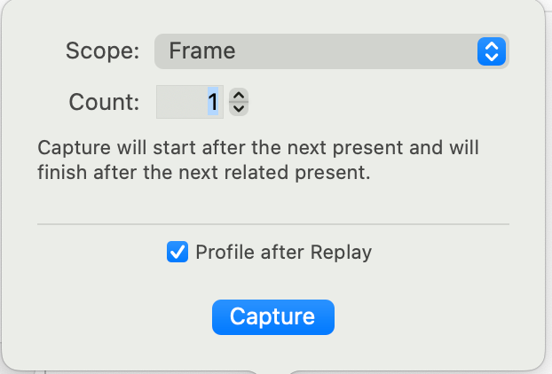
Capture the frame:
Option-click to open up the GPU commands:
Click on the draw call to see the draw results:
On the left you’ll see everything that’s bound to the CPU.
You have:
- two shader functions involved, set up by the pipeline state object.
- An index buffer set up by the
drawIndexedPrimitives method
- Two vertex buffers at slots 0 and 1
Double click on Vertex Attributes:
You can immediately see there’s something wrong here.
The columns are:
- the index number. The number of indices to be rendered is set up in
drawIndexedPrimitives’s indexCount parameter.
- vertex number. In
Quad’s indices array, you match a vertex to each index.
-
position. The GPU thinks that this is a float3 because of the pipeline state’s vertex descriptor. You set this to be MTLVertexDescriptor.customLayout.
-
textureCoordinate. Similarly, this is matched to the pipeline state’s vertex descriptor and is a float2.
- the
out columns are from your shader’s VertexOut structure.
So now that we’ve determined something is off, we can find out why.
There are a number of things to look at.
- The
vertices array
- The index order (order vertices are rendered in)
- The vertex descriptor
Starting with the vertices array. You have 20 floats in Quad’s vertices array, which doesn’t seem to match any layout.
Chapter 4, The Vertex Function, in the Metal by Tutorials book, which doesn’t use a vertex descriptor, suggests this layout:
  var vertices: [Float] = [
    -1, 1, 0, // triangle 1
     1, -1, 0,
    -1, -1, 0,
    -1, 1, 0, // triangle 2
     1, 1, 0,
     1, -1, 0
  ]
And then, instead of using the stage_in attribute (which is only useful when the pipeline state has a vertex descriptor), the chapter uses the vertex function parameter constant packed_float3 *vertices [[buffer(0)]].
However, as you’re doing indexed drawing, you don’t need to duplicate the positions, and can describe the vertices with just four simd_float3s.
The order that your vertices are rendered in is: 0, 3, 2, 0, 1, 3, as specified by indices. The default winding order for a render encoder is clockwise. So each triangle will be rendered clockwise. You can change this before the draw call with renderEncoder.setFrontFacing(.counterClockwise).
If your vertices structure is:
  var vertices: [simd_float3] = [
    [-1, -1, 0],
    [ 1,  1, 0],
    [ 1, -1, 0],
    [ 1, -1, 0]
  ]
Then with your index order, this is how the quad will render:
The blue triangle has a counter clockwise winding, so theoretically shouldn’t render as it’s not facing the right way. (Actually it would because we’re not culling back faces.)
So I can either change vertices, or the index order. I’ll change vertices to:
  var vertices: [simd_float3] = [
    [-1, -1, 0],
    [ 1, -1, 0],
    [-1,  1, 0],
    [ 1,  1, 0]
  ]
This is how the quad will now render:
Both triangles have clockwise winding.
When you create the buffer, you’ll also have to change the length to match the array:
guard let vertexBuffer = device.makeBuffer(
  bytes: &vertices,
  length: MemoryLayout<SIMD3<Float>>.stride * vertices.count,
  ....
Now you have your data in three buffers:
-
vertexBuffer which has a stride of SIMD3<Float>
-
textureBuffer which has a stride of SIMD2<Float>
-
indexBuffer which has a stride of UInt16.
Now we’ll look at the vertex descriptor.
You need to make sure that your vertex descriptor matches the layout of your buffers. You’ll place vertexBuffer in buffer index 0, and textureBuffer in buffer index 1. (Currently you’re placing indexBuffer in buffer index 1, but it’s not necessary to set the indexBuffer as a vertex buffer, as the draw call will do that.)
Take a look at MTLVertexDescriptor.customLayout. This doesn’t match what your data is.
You are setting both the vertex attributes [0] and [1] on bufferIndex 0. Also, you’re only setting layouts[0].stride, and not layouts[1].stride.
Change the vertex descriptor attributes and layouts to this:
static var customLayout: MTLVertexDescriptor {
  let vertexDescriptor = MTLVertexDescriptor()

  //Position
  vertexDescriptor.attributes[0].format = .float3
  vertexDescriptor.attributes[0].bufferIndex = 0
  vertexDescriptor.layouts[0].stride = MemoryLayout<SIMD3<Float>>.stride

  //Texture Coordinates
  vertexDescriptor.attributes[1].format = .float2
  vertexDescriptor.attributes[1].bufferIndex = 1
  vertexDescriptor.layouts[1].stride = MemoryLayout<SIMD2<Float>>.stride

  return vertexDescriptor
}
Because your position array and your texture coordinate array are in two different buffers, you don’t have to worry about offsets. Byte zero in the buffer is always the start of the array. (See the end of the post for an alternative where you can put everything in one buffer.)
With all this in place, build and run, and capture the Metal frame:
You can see that the position is now correct, and your quad is rendering. Your texture coordinates are haywire though.
In Renderer.swift, you set quad.indexBuffer in slot 1. Change:
renderEncoder.setVertexBuffer(quad.indexBuffer, offset: 0, index: 1)
To:
renderEncoder.setVertexBuffer(quad.textureBuffer, offset: 0, index: 1)
The texture buffer is now in buffer index slot 1, and that’s all that’s needed to make it work. You got your UV coordinates correct  ! (except you shouldn’t be scaling the UV coordinates)
You’ll notice that the logo stretches to match the size of the window. This is because you are using normalised device coordinates (ie relative to the size of the window). Until you have perspective working, that’s what will happen.
Also, the corner transparency doesn’t work. You’ll have to test the alpha and discard the fragment.
Here’s the working project.
PictureEditor.zip (1.7 MB)
I think one of the hardest things to understand in the early days is the vertex descriptor. If you use the stage_in attribute in your vertex function (and it is the most efficient for the rasterizer), then the vertex descriptor has to exactly match the way you present your data.
I promised an alternative way of presenting your data.
Instead of placing your data in two buffers, you can create a structure of data.
In Quad.swift, I created a structure:
struct Vertex {
  var position: simd_float3
  var textureCoord: simd_float2
}
and removed any references to textureBuffer.
I changed the vertex descriptor to match this structure.
  static var customLayout: MTLVertexDescriptor {
    let vertexDescriptor = MTLVertexDescriptor()
    var offset = 0

    //Position
    vertexDescriptor.attributes[0].format = .float3
    vertexDescriptor.attributes[0].bufferIndex = 0
    vertexDescriptor.attributes[0].offset = 0
    offset = MemoryLayout<SIMD3<Float>>.stride

    //Texture Coordinates
    vertexDescriptor.attributes[1].format = .float2
    vertexDescriptor.attributes[1].bufferIndex = 0
    vertexDescriptor.attributes[1].offset = offset

    vertexDescriptor.layouts[0].stride = MemoryLayout<Vertex>.stride

    return vertexDescriptor
  }
The difference is that instead of having two buffers:
position, position, position, position
and
coord, coord, coord, coord
Your data now is in one buffer, but each vertex is interleaved.
position, coord, position, coord, position, coord, position, coord
So for this second alternative, you only have to describe buffer[0], and specify the offset of the coordinate from the start.
Notice that the structure in the vertex shader doesn’t change at all. The vertex function receives position as a float4. That’s the magic of the stage_in attribute, which looks at the pipeline state’s vertex descriptor and automatically reformats the data.
This is the project with these changes:
PictureEditor2.zip (1.7 MB)


